
Almost everything written about the Omnichord strumplate calls it a capacitive touch sensor. I believed it too, until I put a meter on one.
It isn't. Your finger's capacitance does nothing. Hover over the plate, wave at it, drag a fingertip across the surface without pressure and you get silence. It's a much dumber and more physical device than that, and knowing what it actually does is what made the rest of this project possible.
How it works
A bare strumplate PCB has two interleaved sets of conductors. One set is the note contacts, one per note across the strum. Woven between every one of them, like the teeth of a comb, is a second conductor carrying +12V.
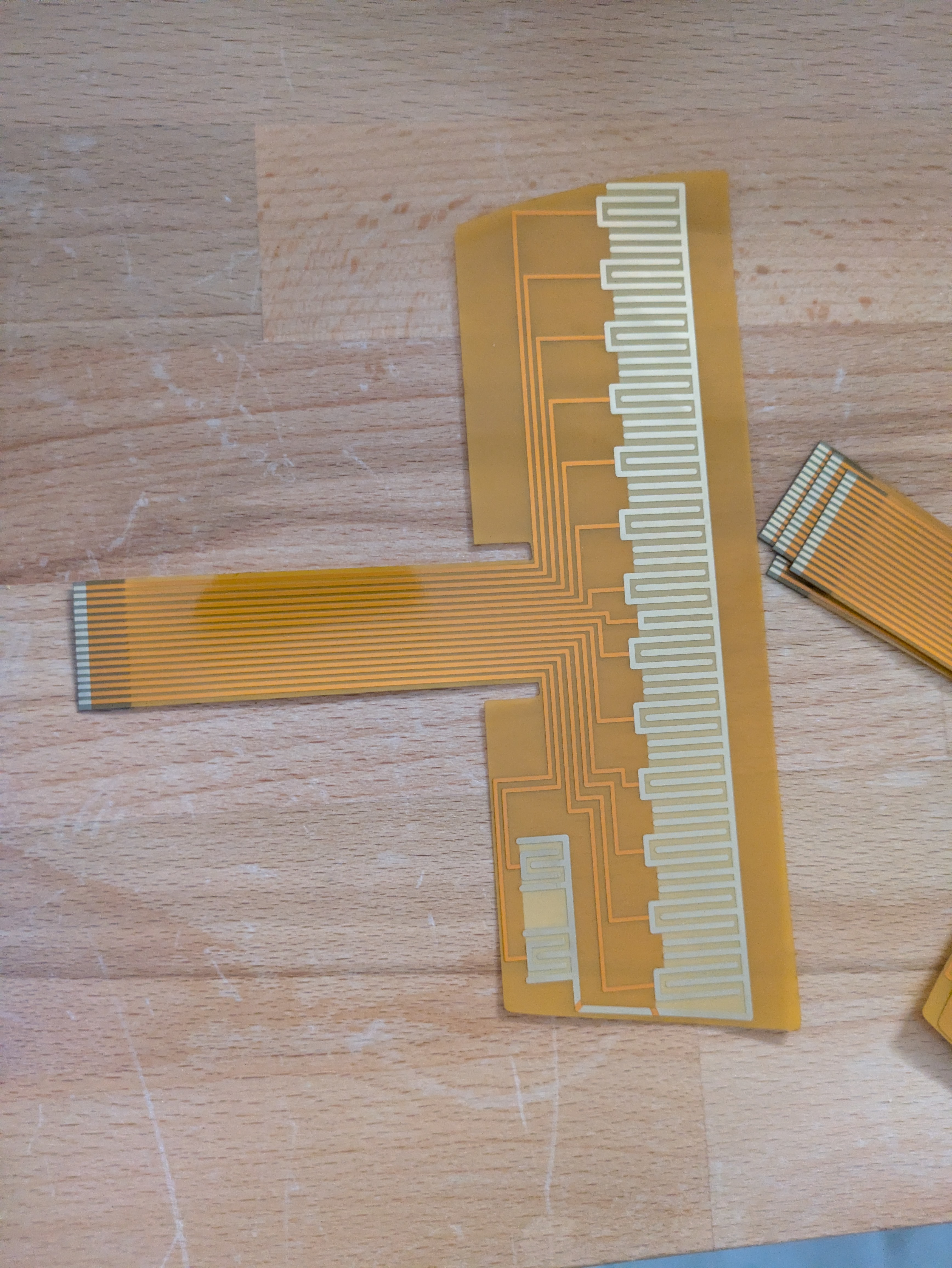
The note contacts do nothing by themselves. A note fires when its contact gets shorted to the neighboring tooth of the 12V comb. That's the whole mechanism. It's a switch.
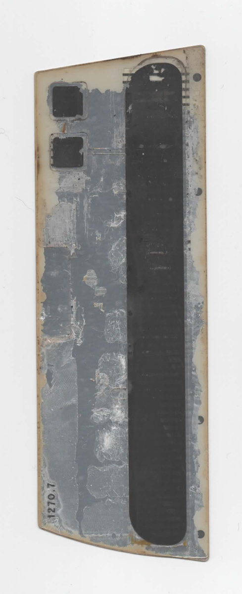
Skin isn't a good enough conductor to do that shorting, so Suzuki laid a carbon layer over the top of the traces. Press down and the carbon deflects into contact with the conductors underneath, bridging note to comb. The carbon is the switch. Your finger is just what presses it.
This reframes the failure modes. A dead note isn't a sensor that stopped sensing, it's a short that stopped shorting: worn-through carbon, a cracked trace, corrosion between the comb and a note contact. Mechanical and electrical problems with mechanical and electrical fixes, which is why reproducing the thing is tractable at all.
The continuous strip
On the original plate, that carbon layer is one continuous strip. A single unbroken sheet of conductor running the length of the plate, sitting over every note contact and every comb tooth at once.
Press it and you aren't bridging one note. You're pressing on a shared conductive path that touches everything under your finger, and which notes fire depends on exactly where the carbon lands. Neighbors come along for the ride. Picking out one note deliberately is hard, and it's hard because the switch layer can't tell adjacent notes apart.
The Omnichord's reputation for being loose and splashy comes from this. I've always liked that about it, and I'm not interested in arguing that Suzuki was wrong. But it isn't inherent to the instrument. It's a consequence of one continuous strip of carbon, chosen in 1981, almost certainly because it was the cheapest thing that worked.
Cutting it up
If a continuous layer can't distinguish adjacent notes, make it discontinuous.
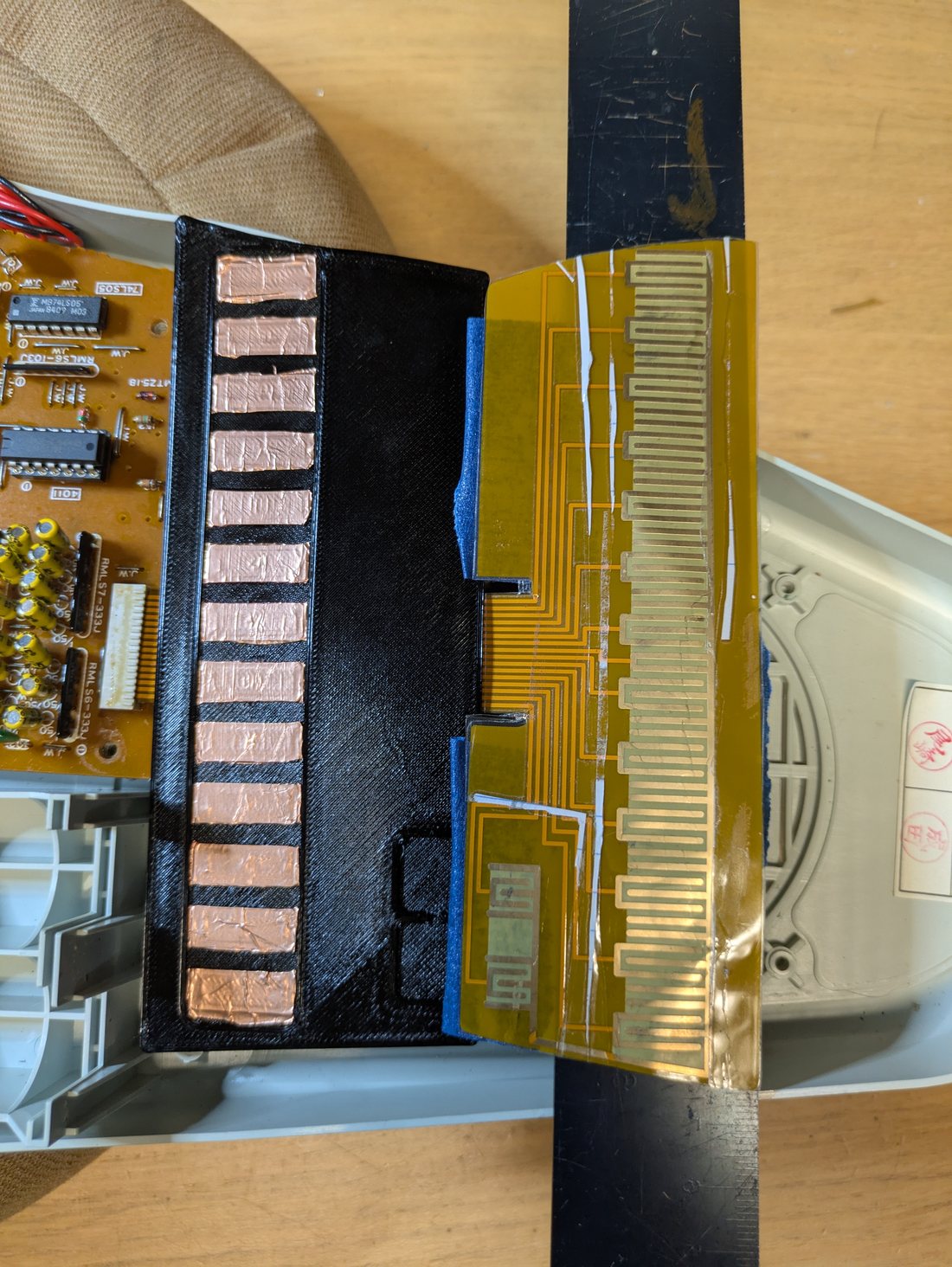
My top plates break the conductive layer into 12 or 13 sections, one per note (The OM-27 only has 12 notes available). Each note contact gets its own isolated pad bridging it to the comb, electrically separate from its neighbors. Press one and you short exactly one note. Nothing bleeds, because there's no shared path to bleed through.
You can feel each note as a distinct thing under your finger, and you only play two at once when you meant to.
It's not a free upgrade. The continuous strip is what gives you that smeared, liquid glissando across the plate, which is a big part of what an Omnichord sounds like. Cutting the carbon into sections puts boundaries where there weren't any. You get articulation and you give up some of the smear. Which one you want depends on what you're playing, and until now nobody got to pick.
Two parts, and the circuit board is the boring one
The rebuild splits into two pieces that don't depend on each other much.
The flex PCB carries the note contacts and the 12V comb. It's the substrate, and it's what replaces your dead original. I drew it in KiCad and had it fabbed as flex, because the plate has to be thin and it has to conform. Rigid FR4 was never going to work. Version 1.0 for the OM-84 works: it strums, it responds across the plate, and it feels like an Omnichord. At 0.11mm it might be a little too thin. That's a knob I'm still turning.
Stiffening a board that's too floppy
0.11mm is thin enough to be a nuisance to handle, and there are two ways I've been adding stiffness back.
The first is polyimide stiffener, which is the normal way to do this. On the OM-84 v1.0 I only put it at the connector end, where the board meets the ribbon. On the OM-27 v1.0 I've run stiffener across the whole plate. That board hasn't come back from fab yet, so I don't know how it plays. I'll report back.
The second one I did not expect to work: a laminating machine. An ordinary office laminator. Mask off the contact pads and the gold teeth at the connector, run the board through once or twice, and it comes out substantially stiffer. It's made a real difference on the thin boards, and it costs nothing.
If you're building from the files in the repo, the masking matters. Anything that ends up laminated over is a contact that no longer makes contact. Cover the pads and the connector teeth before the board goes through. I recommend paper or anything non-adhesive -- the flex PCB is far too fragile to risk removing tape.
The 3D printed top plate carries the conductive material. This is the part that decides how the instrument plays, and it's separate from the board and swappable. That means one sensor underneath and any number of top plates over it, and swapping the top plate changes how the instrument plays.
Which conductor
The switch layer has to conduct, survive a few thousand presses, and feel right. Suzuki used carbon. I've been working through the alternatives on printed plates:
- Copper tape. Great conductor, easy to cut cleanly into sections.
- Faraday fabric. Conductive textile, and it has some give to it. Different feel entirely.
- Carbon-graphene paint. Closest to the original in spirit, brushes onto a printed surface.
- Copper paint. Lower resistance than carbon, paintable, wears differently.
Different resistivity, different durability, different response under a fingertip. Because the top plate comes off, I can run all of them against the same sensor board, which is about as clean a test setup as I could ask for.
The thing I actually want to know is how they age. The original plates died partly because the carbon wore through. Does a copper film hold up better or just fail in a new way? Does graphene paint survive a fingernail? I don't have years of data on any of this and I'm not going to pretend I do. Comparing the materials is on the to-do list in the repo, and it's the experiment I most want to run.
Printing the plate opens up the physical side too. Tactile note markers you can find by feel, the way a guitarist finds a fret. Textures. And the sections don't have to be 12 equal pieces just because there are 12 notes. One might even consider a completely different note layout, perhaps even something non-linear like the alternative plate of the minichord.
The pads that don't do anything
Here's something I did not expect to find, and I still don't have an answer for it.
Alongside the note contacts, the OM-84 plate has two more pads. One of them is the reset touchpoint, which is documented and does what it says. The other one sits above it, and it isn't documented anywhere I've looked. It's normally hidden under the faceplate, so unless you have the instrument apart you would never know it was there. Its traces run a short distance and then stop. They go nowhere.
I have no idea what it was for. A feature that got cut late? A test point? A shared board layout across models where the OM-84 just doesn't use that one? All of those are guesses.
What it is, concretely, is a working point of contact that the instrument isn't currently using. Which means it's a place you could hang something. Trigger a different sound, fire a modification, add a control the instrument never had. I haven't done anything with it yet, but I've reproduced it faithfully on the new boards rather than deleting it, because a contact point that nobody is using is more interesting than a blank space.
Looking at the early OM-27 boards, it appears there might be three of these.
If you know what these pads were for, I would very much like to hear from you. Service documentation, a factory schematic, a memory of a feature that didn't ship, anything. Open an issue on the repo or get in touch.
What's still rough
- The gold finger pitch at the ribbon connector needs tightening. I get insertion errors sometimes..
- The SCAD and STL curves aren't right yet. The files in the repo are a starting point, not print-ready parts, and they're labeled that way.
- The OM-27 board is out at fab and I haven't got it back yet. It's the first one with stiffener across the whole plate, so I don't know yet whether that helps or whether it kills the feel. The OM-84 went first because it's what was on the bench.
Why it's all public
I didn't invent anything here. I looked at how a forty year old switch works, drew the pattern in KiCad, and paid a board house to make it. The techniques are ordinary. The reason it hadn't been done is that nobody had drawn the files and put them somewhere public. Special thanks to AJ & Patterson EP Service for having the courage to teardown an OM-84 plate missing a few notes and share high-quality scans -- this project wouldn't exist otherwise!
So they're public: github.com/keyandcableco/Omnichord-Strumplates. If you can order a PCB you can have a strumplate. You don't need me for it. The part was only scarce because nobody had made more, and that was the one thing keeping a lot of these instruments in closets.
Help wanted
- The SCAD/STL curves for the faceplate of the OM-27. If you're better at parametric CAD than I am, and plenty of you are, this is the most useful thing you could do.
- Measurements from other models, the OM-36 especially. I can't design for a plate I've never held.
- High-res photos of working and failed plates, any model. Failures are as useful as working ones.
- Conductive material experience. If you've used conductive paints, films, or fabrics for contact switching and have opinions about how they wear, I want to hear from you.
- Any idea what the undocumented pads are for. The one above the reset point on the OM-84, and whatever the OM-27 has going on. Schematics, service docs, or just a good theory.
Issues and pull requests are open.