
The OM-100 and the OM-200M are the same instrument. Same PCB, same firmware, and even the ROM is labeled "OM100/200." Suzuki populated more of the board on the OM-200M, and one of the things left off the OM-100 is the MIDI output.
So you're not "adding MIDI" to an OM-100. The firmware already generates the data; all you have to do is build the output stage that it shipped without.
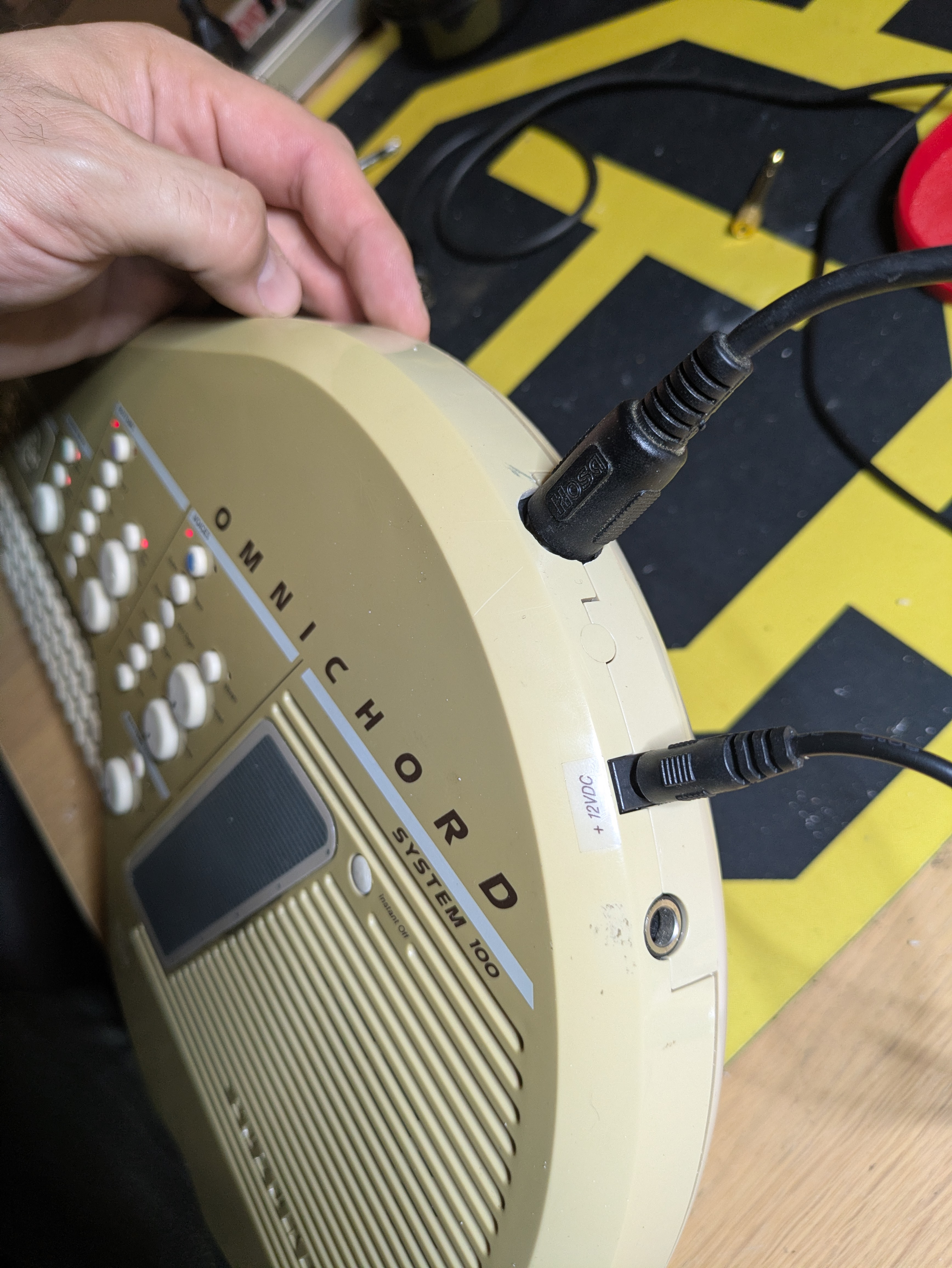
Suzuki even left the footprint for a MIDI jack on the case; remove some plastic, install a few components, and you've got yourself MIDI output on an Omnichord OM-100. Call it the OM-100m.
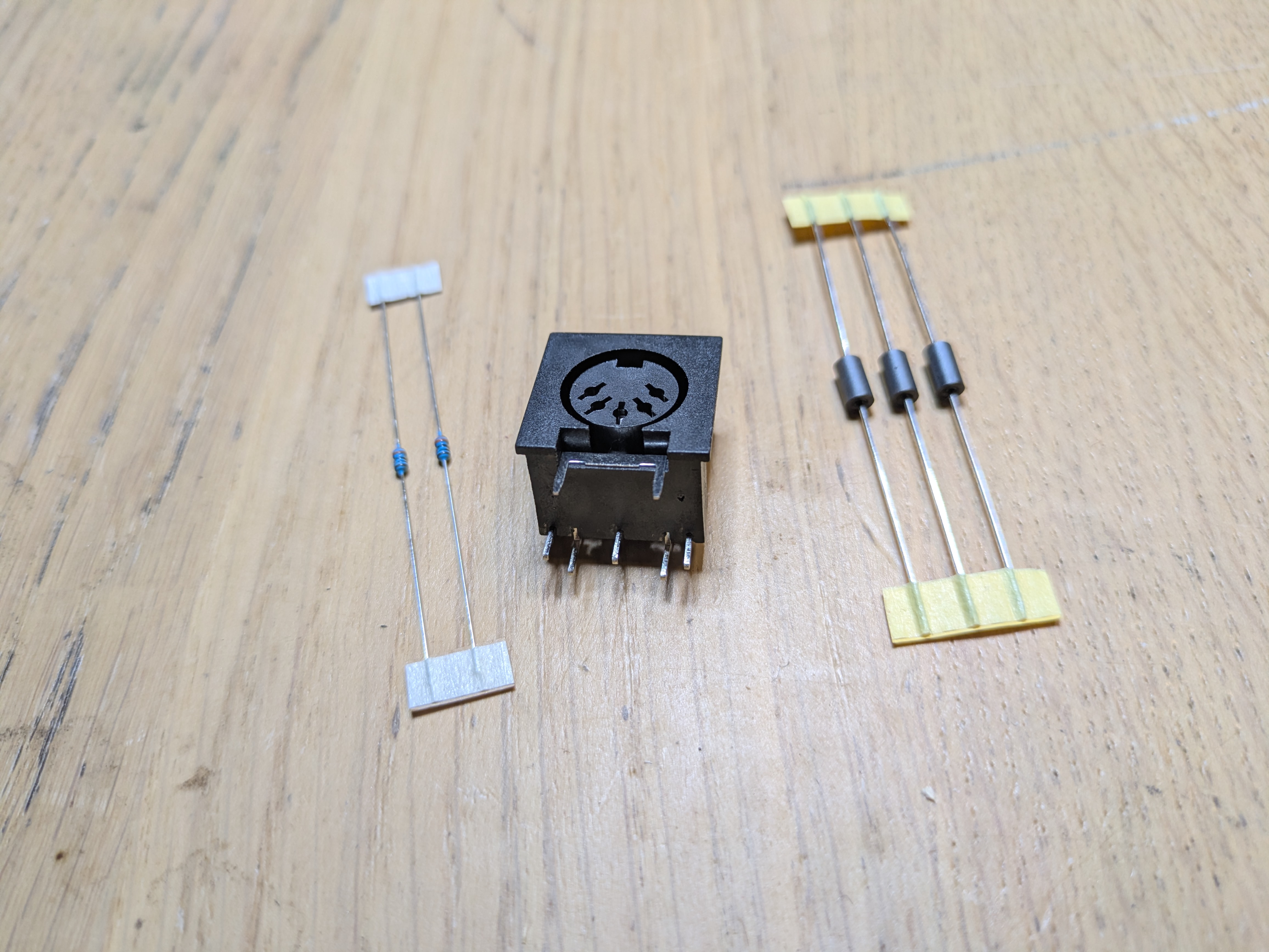
Parts and tools
Parts
- 5-pin DIN MIDI jack, panel mount. Example listing.
- Two 330Ω resistors, 1/8W. Use 1/8W if you want to match the footprint.
- Ferrite beads for the three positions that call for them. Jumper wire across those spots works if you don't have beads on hand; they're there for noise suppression on the output lines, not for basic function.
Tools
- Soldering iron, flux, solder
- Dremel or similar rotary tool
- Files or a small sanding drum
1. Find the MIDI section, desolder some pads
The MIDI jack normally lives on the power board near the footswitch and the power and output jacks. You'll want to remove this small board; 3 screws and a few wire harnesses will allow this.
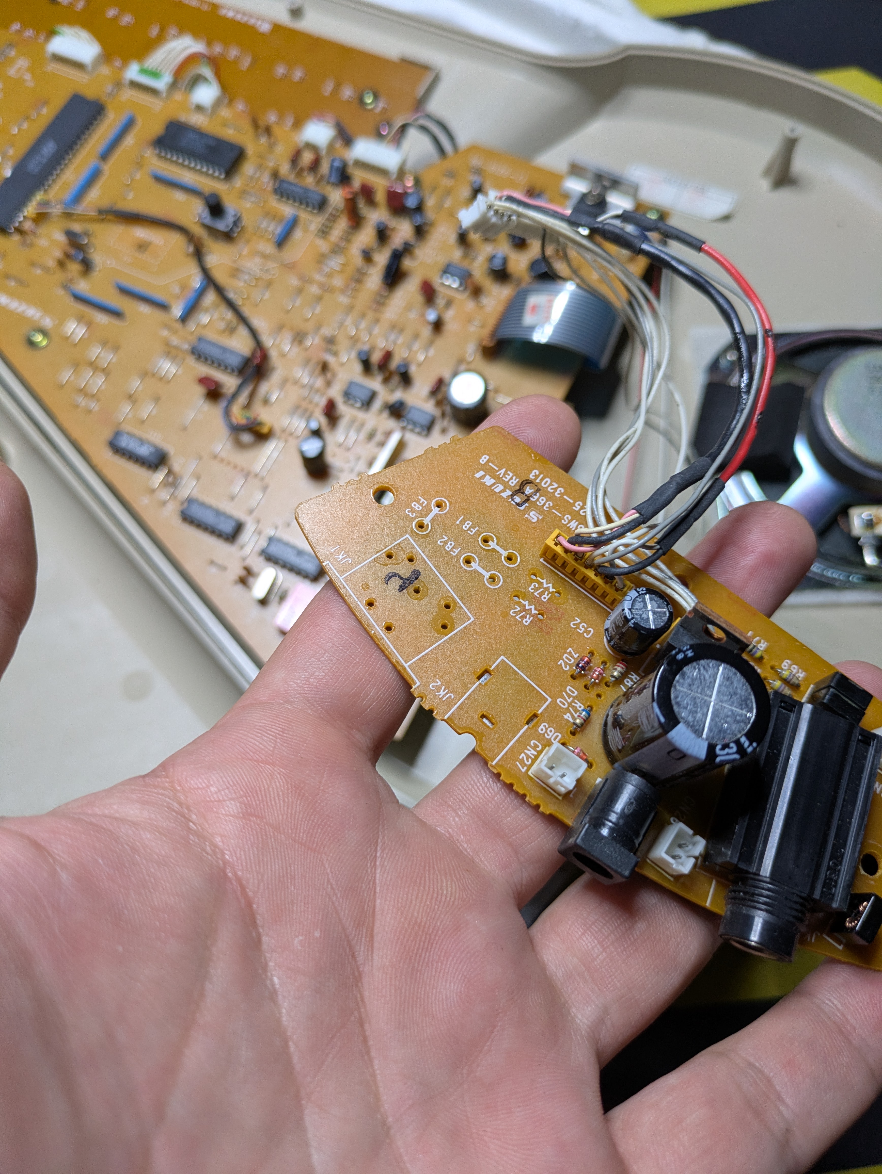
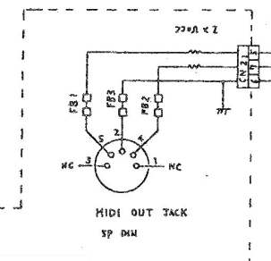
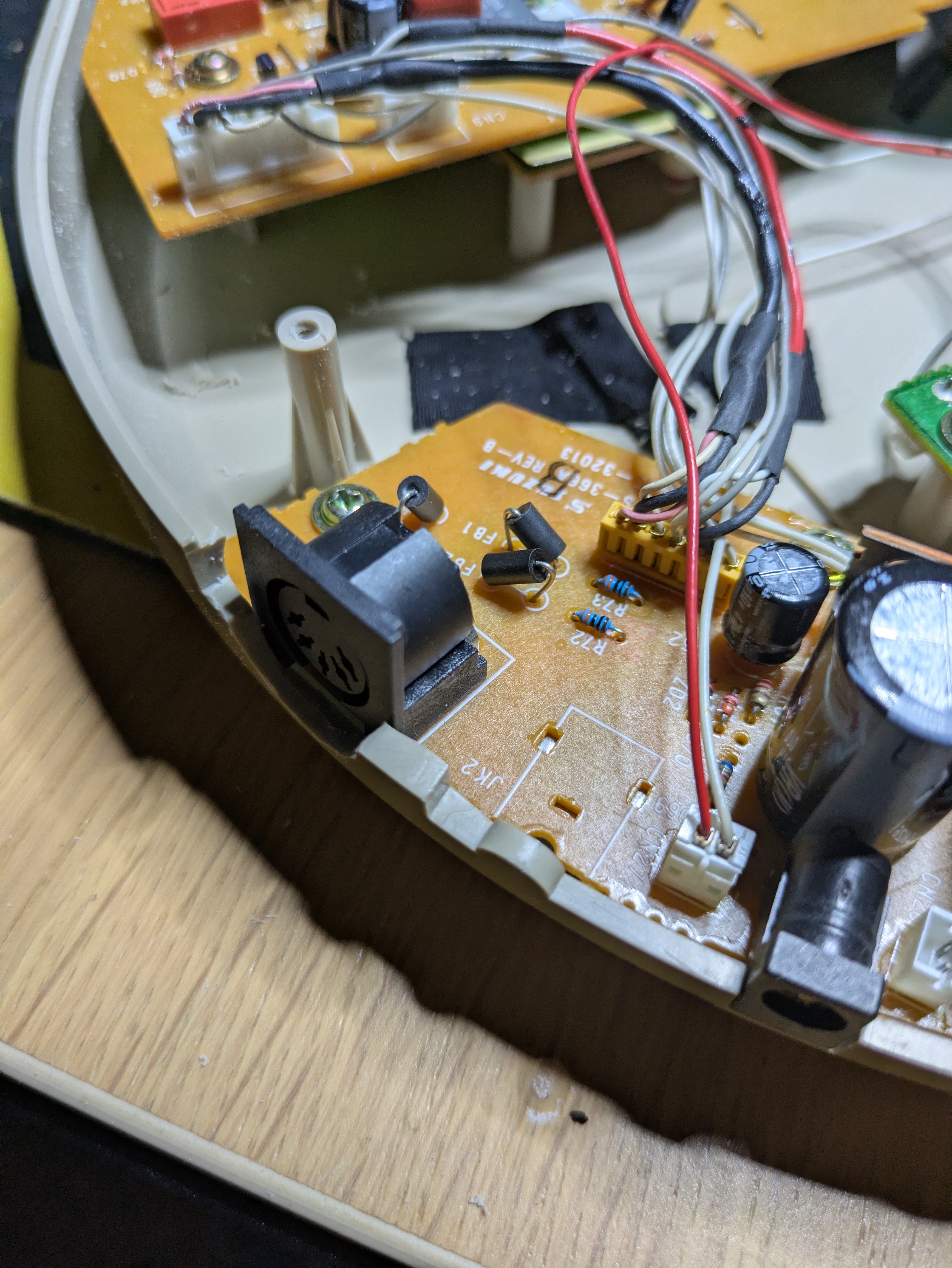
It is necessary to desolder the unused pads for FB1, FB2, and FB3, as well as R72 and R73 and the MIDI jack itself. Next we populate.
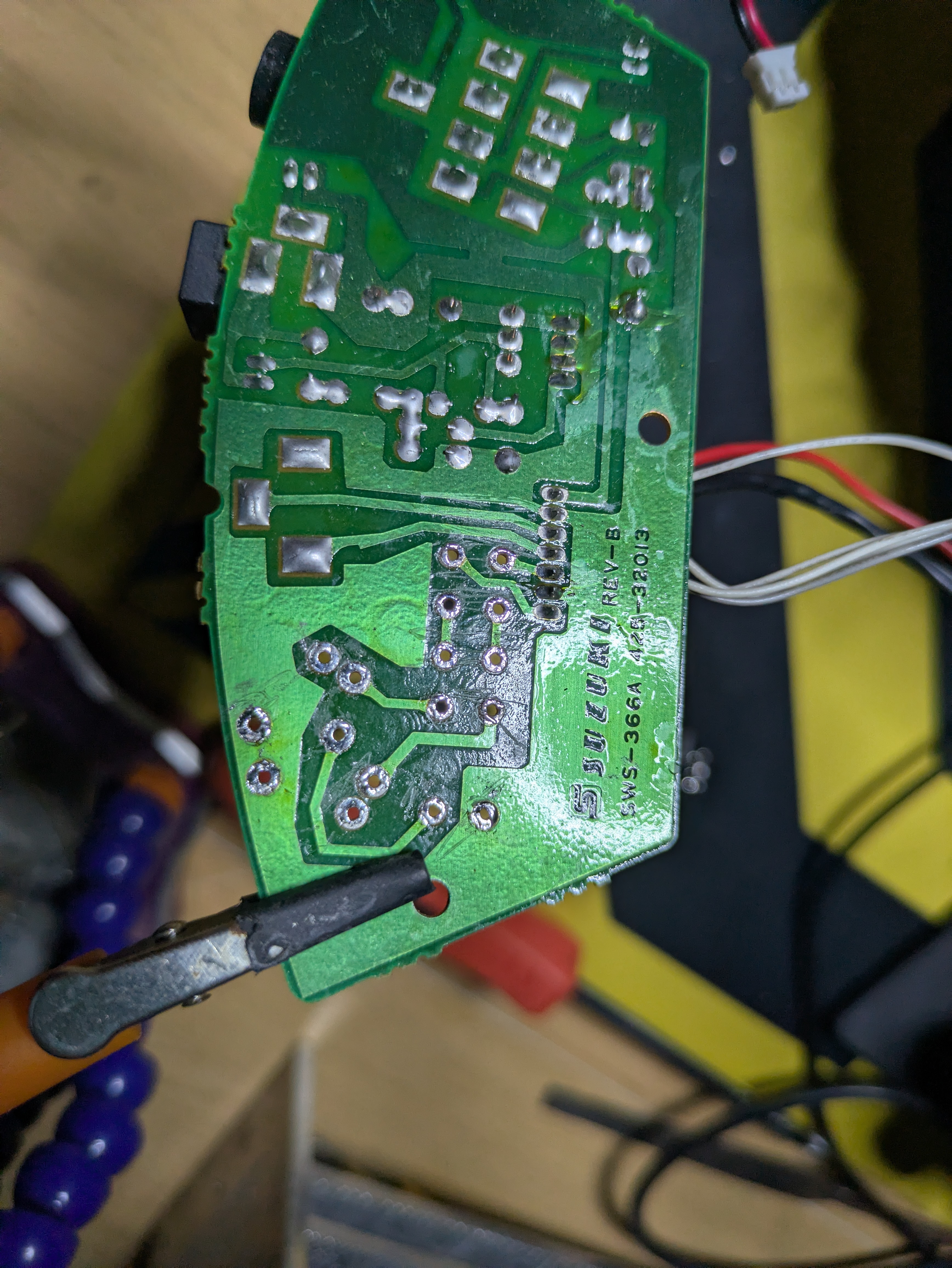
2. Fit the resistors and beads/jumpers
Install the two 330Ω 1/8W resistors and solder in place.
Fit ferrite beads in their footprints if you have them. If you don't, jumper across with wire. The beads suppress noise on the output lines; they aren't doing anything for basic operation.
3. Solder the MIDI jack
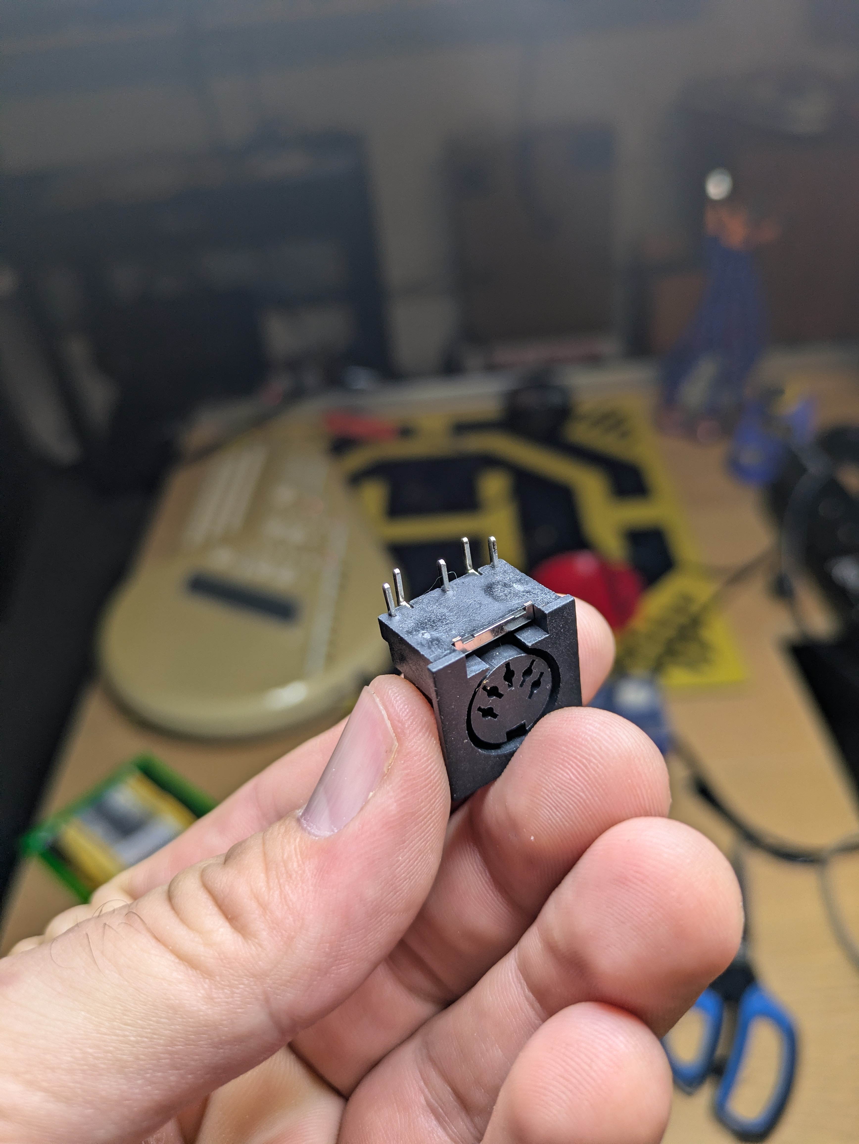
If you're using modern, commonly-available MIDI DIN connectors like this, snip off the two front pins; they aren't going to fit the footprint on the OM-100, and we don't need them anyway. Then fit the jack into the 5 rear pads and solder.
4. Drilling out the case
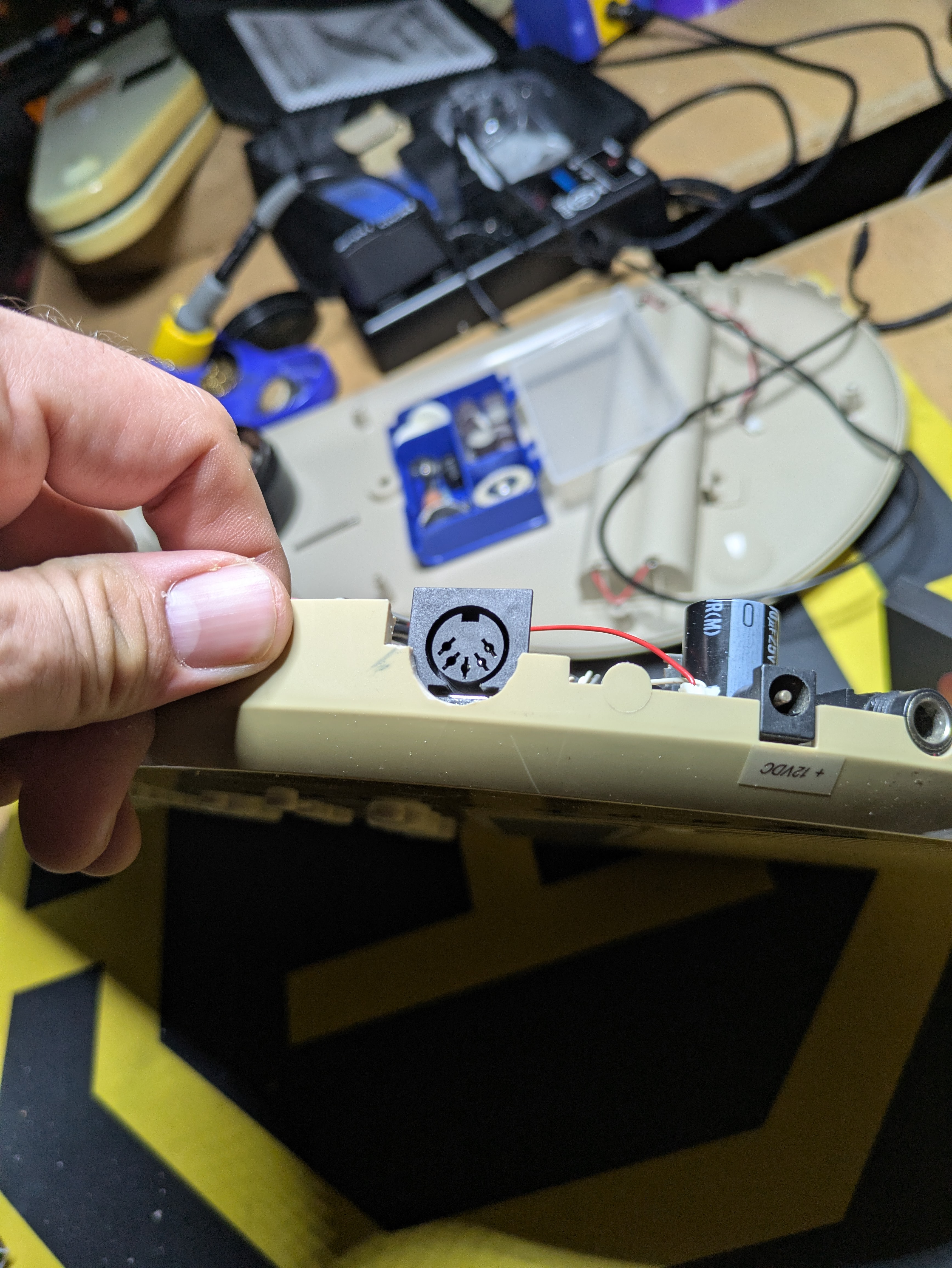
Suzuki made the location of the port very easy to find; clearly they used the same case as the OM-200M. Removing this circle of plastic without making a mess is the real challenge of this project. I opt to wrap the OM-100 in plastic wrap and painter's tape to keep from throwing plastic shards into the circuitry, but it's probably most wise to do a complete disassembly.
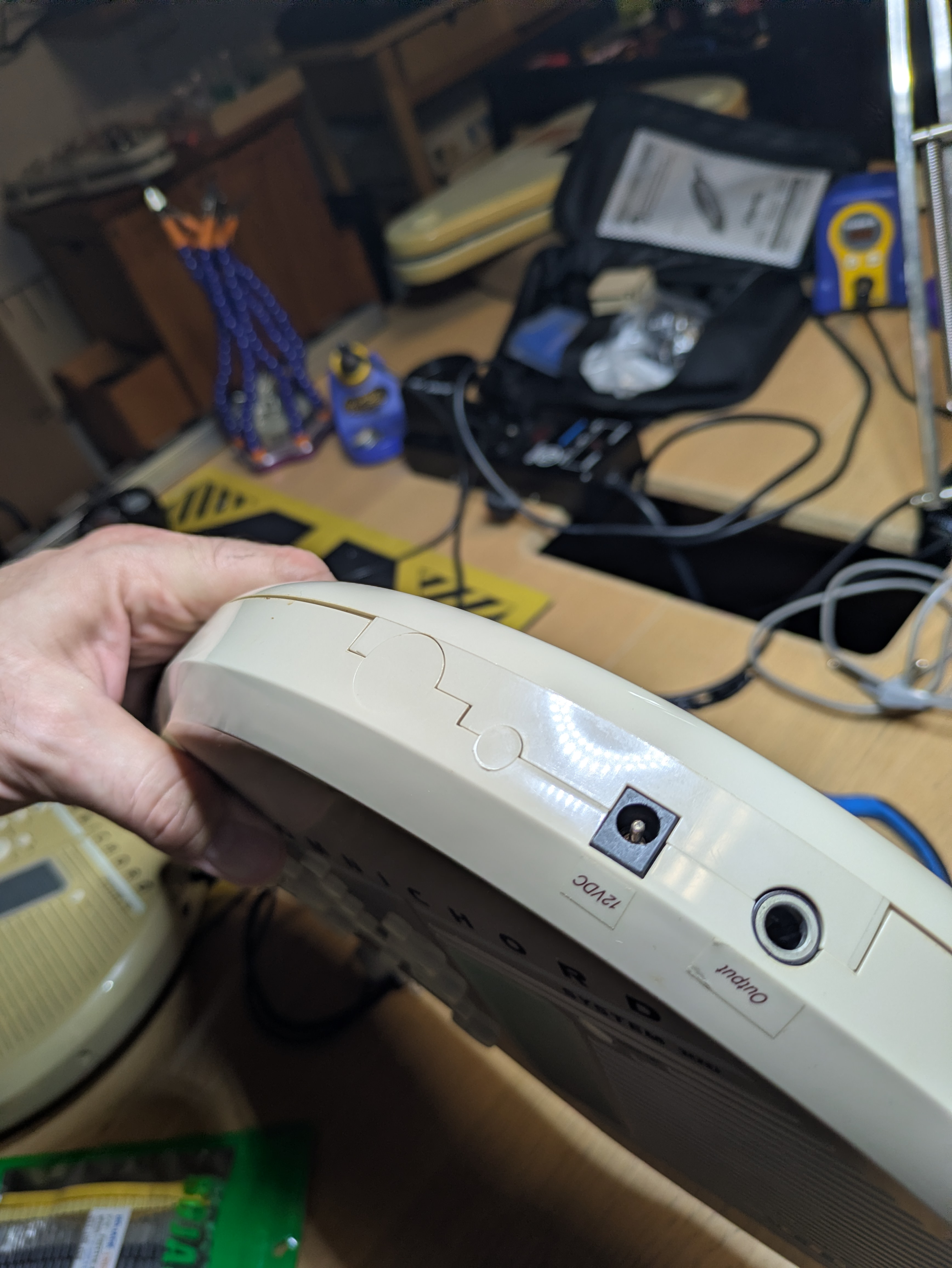
Then the question of "how." If you trust yourself with a Forstner bit, it's not a bad method, but drill a pilot hole and be sure the blade is sharp. If not, it's easy to slowly grind away with a sanding barrel on a rotary tool like a Dremel. I recommend this method because you'll likely have to remove some extra plastic to get a good solid fit for your chosen MIDI jack.
Or go at it with files. Whatever you do, just take your time and do it well; you'll thank yourself later.
5. Test before closing
Check continuity from the jack pins while everything's still open.
Then connect to a MIDI interface and any monitor utility, and play. You should see output arriving as described in the OM-200M documentation.
| MIDI channel | Transmits |
|---|---|
| OMNI | All signals |
| 1 | Strumplate |
| 2 | Chords |
| 3 | Walking bass |
Close it up.
What else is on that board
MIDI is the easy one. Suzuki left several other areas unstuffed on the OM-100, and they line up with the rest of what the OM-200M offers:
- Chord memory; a connector pair with an associated diode, populated on the OM-200M.
- Melody keyboard; the OM-200M's added keyboard section.
- Footswitch control; a small resistor and capacitor network with the shape of a switch input.
I'm still tracing those and won't publish values until I've confirmed them on the bench. The principle is the same though: the board and firmware are shared, so most of what separates the two models is parts that were never fitted.