A while back, Filip Kindt wrote up replacing the top octave generator in a Hammond X-5[1] using an RP2040 and some PIO trickery. That project replaced the MM5833, which generates 7 of the top-octave square waves the organ needs. The solution was elegant: let the PIO hardware count clock cycles and flip output pins at the right moments. No software intervention required once it's running. Filip noted at the end that the RP2040's 8 state machines were the limiting factor — a chip with more PIO resources could handle a full 12-tone TOG. I read that, filed it away, and eventually found myself staring at a dead Omnichord that needed exactly that. This blog post tracks my thinking on this subject before making hardware decisions.
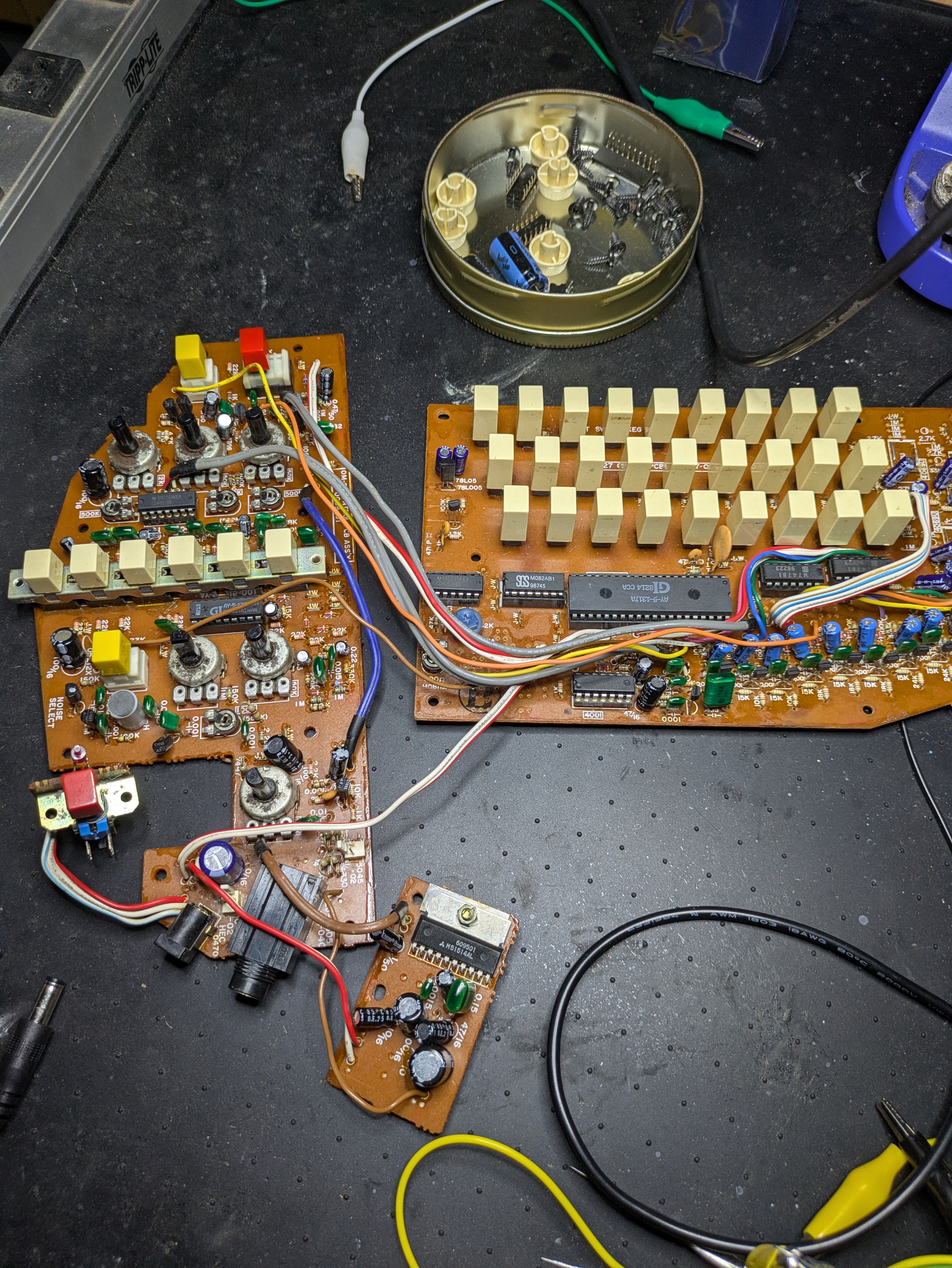
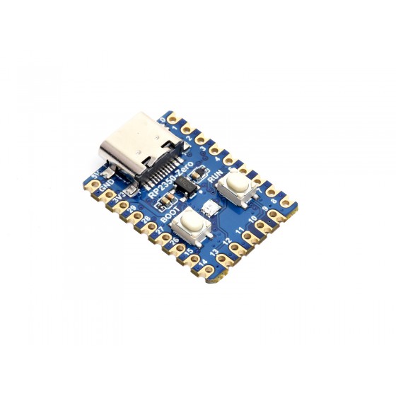
The Suzuki Omnichord OM-27's M083A top-octave generator outputs all 12 chromatic tones — more than the Hammond's MM5833. The RP2350 has 12 PIO state machines across its two PIO blocks, which is exactly enough. But the M083A isn't even the hard part. The real problem is the AY-5-1317A sitting next to it — a General Instrument chord logic IC that reads the chord button matrix, selects the right frequencies for the pressed chord, and routes them to a pair of M747 octave dividers that feed the strum plate. It's the whole musical brain of the instrument, and it's quickly becoming completely unobtainable.
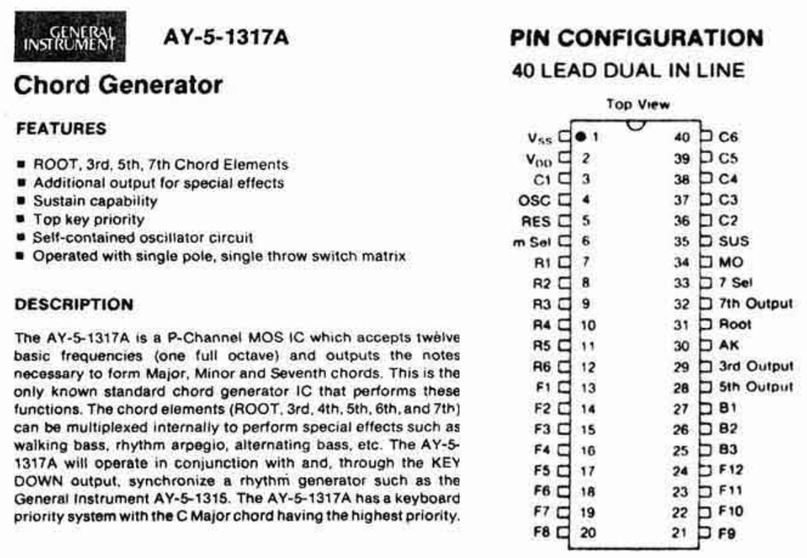
What the AY-5-1317A actually does
The AY-5-1317A is a 40-pin P-channel MOS IC. It accepts 12 top-octave frequencies on pins 13–24 from the M083A (one full chromatic octave, B down to C), reads a key matrix on pins 7–12 and 36–40, and outputs up to five chord tones on pins 28–32 and 34. It also accepts a 3-bit bass select input from the AY-5-1315 rhythm chip that sequences which chord tone plays as the auto-bass line in sync with the drum patterns.
The OM-27's key matrix is 3 rows × 6 column pins, covering 9 chord roots via tritone sharing — three of the column pins serve two roots each. Pin 39 covers both Eb and A, pin 40 covers Bb and E, and pin 3 covers F and B. Each physical button connects only one root to one row, so the shared pin is never actually ambiguous during normal playing.
The power supply situation
The AY-5-1317A is P-channel MOS. Its datasheet specifies VDD = -15V and VSS = 0V, which is General Instrument's standard P-channel test configuration. The OM-27 has no negative rail — just +12V and +5V. Suzuki almost certainly wired VSS to +12V and VDD to GND, the standard trick for running P-channel ICs on a positive supply.[3] Under this configuration: logic HIGH = +12V, logic LOW = GND. This is consistent with pin 5 (reset/mute) sitting at +12V at rest and being triggered by grounding it.
Replacing four chips with one
Replacing the AY-5-1317A also makes several of the surrounding chips unnecessary:
| IC | Role | Approach |
|---|---|---|
| AY-5-1317A | Chord logic, key matrix, frequency routing | RP2350 firmware in this socket |
| M083A | Top-octave frequency generation | PIO state machines, generated internally |
| 4069 | RC oscillator clocking the M083A | Not needed; 78L05 repurposed for RP2350 power |
| 4001 | NOR gate routing 5th or 7th to bass M747 chain depending on chord type | Bypassed — firmware outputs the correct note directly to pin 34 |
The 78L05 that previously powered the 4069 (dropping 12V to 5V) gets repurposed to feed the RP2350-Zero's VBUS. The AY-5-1315 rhythm chip, 4011 percussion logic, and all downstream audio circuitry are completely untouched.
The M747 octave dividers also need replacing — they're not cheaply obtainable either. The CD4520 is a functionally equivalent substitute (dual 4-stage binary counter, still in production) that covers the three divide stages the OM-27 needs. A passive adapter board in each M747 socket handles the pin translation, no active components required.
The firmware
The firmware is published as The OpenChord Project, split into instrument-agnostic core modules and an OM-27 specific config. The idea is that the core logic can be reused for other instruments with dead top octave generators and chord logic ICs.
Frequency generation
Each chord tone is generated by a PIO state machine counting half-period cycles from the 125 MHz system clock. No external oscillator is needed — the RP2350's internal PLL gives more than adequate pitch stability for this application.
@rp2.asm_pio(set_init=rp2.PIO.OUT_LOW)
def freq_gen():
    pull(noblock)       # grab new counter if available, else keep Y
    mov(y, osr)
    wrap_target()
    set(pins, 1)
    mov(x, y)
    label("hi")
    jmp(x_dec, "hi")
    set(pins, 0)
    mov(x, y)
    label("lo")
    jmp(x_dec, "lo")
    wrap()
Five state machines run simultaneously: ROOT, 3RD, 5TH, 7TH, and MO (the auto-bass output). Changing chord pushes new counter values to the running SMs, so there's no audible discontinuity between chords.
Extended chord types
The original AY-5-1317A supported major, minor, and dominant 7th. With the chord logic in firmware, additional chord types come essentially for free by detecting button combinations:
| Button gesture | Chord |
|---|---|
| Single button | Major / Minor / Dominant 7th |
| Minor + 7th, same root | Minor 7th |
| Major + 7th, same root | Major 7th |
| Major + Minor, same root | Diminished |
| All three, same root | Augmented |
| Two roots, interval of a 4th | Sus4 |
| Two roots, interval of a 2nd | Sus2 |
| Two roots, other interval | Slash chord |
A solder jumper enables Barry Harris mode, changing major chords to major 6th, minor to minor 6th, and the diminished to fully diminished 7th. The AY pin 5 reset signal is repurposed as a modifier button — holding it shifts all chord roots by a semitone, revealing Gb, Db, and Ab which the original circle-of-fifths layout couldn't access.
Auto-bass
The AY-5-1315 rhythm chip drives a 3-bit signal into the AY-5-1317A (pins 25–27) that selects which chord element plays as the bass note in sync with the drum pattern, coming out on pin 34. That path is internal to the AY-5-1317A and has nothing to do with the 4001. The 4001 is a separate circuit — it NORs the 5th output (pin 28) and the 7th output (pin 32) to route the appropriate tone to the bass M747 chain depending on whether a dominant 7th chord is selected. In the firmware this decision is made directly from the chord type, so there's no need for gate logic.
RP2350 Errata 9
The RP2350 has a silicon errata (Errata 9)[4] where GPIO pins configured with PULL_DOWN can latch at around 2.1V when floating, which makes them unreliable as sense inputs. With six key matrix column pins spending most of their time floating between button presses, this matters. The workaround is to use PULL_UP instead and drive the matrix rows LOW during scanning — a pressed button then pulls the column LOW rather than HIGH. The firmware handles this already.
GPIO map
| GPIO | Function | AY-5-1317A pin |
|---|---|---|
| 0 | ROOT output → CD4520 #1 clock A | 31 |
| 1 | 3RD output → CD4520 #1 clock B | 29 |
| 2 | 5TH output → CD4520 #2 clock A | 28 |
| 3 | 7TH output → CD4520 #2 clock B | 32 |
| 4 | MO / auto-bass output | 34 |
| 5 | 7th Select drive (LOW = 7th active) | 33 |
| 6 | Row drive: Major | 11 + 12 |
| 7 | Row drive: Minor | 9 + 10 |
| 8 | Row drive: Seventh | 7 + 8 |
| 9 | Col sense: Eb / A | 39 |
| 10 | Col sense: Bb / E | 40 |
| 11 | Col sense: F / B | 3 |
| 12 | Col sense: C | 36 |
| 13 | Col sense: G | 37 |
| 14 | Col sense: D | 38 |
| 15 | MIDI TX (optional) | — |
| 16 | Power enable | — |
| 17 | Any Key Down drive | 30 |
| 18 | Memory switch input | 35 |
| 19 | Modifier button input (was reset/mute) | 5 |
| 20 | Bass select B3 from AY-5-1315 | 25 |
| 21 | Bass select B2 from AY-5-1315 | 26 |
| 22 | Bass select B1 from AY-5-1315 | 27 |
| 23 | JP1: flat / sharp modifier select | — |
| 24 | JP2: Barry Harris mode | — |
| 25–29 | Unassigned | — |
What's next
The firmware is written but the hardware hasn't been tested yet. Before anything else:
- Scope the AY-5-1317A output pins to confirm voltage swing and verify the NPN transistor output circuit
- Try direct GPIO connection to the CD4520 clock inputs — 3.3V may be sufficient without transistors
- Build the CD4520 adapter boards and verify they divide correctly
- Bench test with the OM-27 PCB — minimum wiring is power + 5 tone outputs + key matrix
Everything is up at github.com/keyandcableco/openchord-project. The core modules are written to be instrument-agnostic, so if you're dealing with a similar problem on a different instrument, it may be a reasonable starting point.
More updates once it's actually making noise.
- Filip Kindt, "Replacing the top octave generator in a Hammond X-5 with an RP2040", cctv.fm, 2024. ↩
- General Instrument Corporation, AY-5-1317A Chord Generator datasheet. Copies circulated in the vintage synth repair community; no official online archive known. ↩
- This interpretation is inferred from the OM-27's known supply rails (+12V, +5V) and the behaviour of pin 5, and has not been verified with an oscilloscope. The AY-5-1317A datasheet specifies standard conditions of VDD = −15V, VSS = 0V. ↩
- Documented as RP2350-E9, "Latching behaviour on Bank 0 GPIO pull-down resistors," in the RP2350 datasheet (p. 1340). First reported publicly by Dangerous Prototypes; further discussion at Hackaday and the Raspberry Pi forums. Note that several community members have found the latch can occur even without PULL_DOWN enabled. ↩
- Erich Izdepski, erichizdepski.wordpress.com. Schematic scans and repair notes for the Omnichord OM-27. ↩